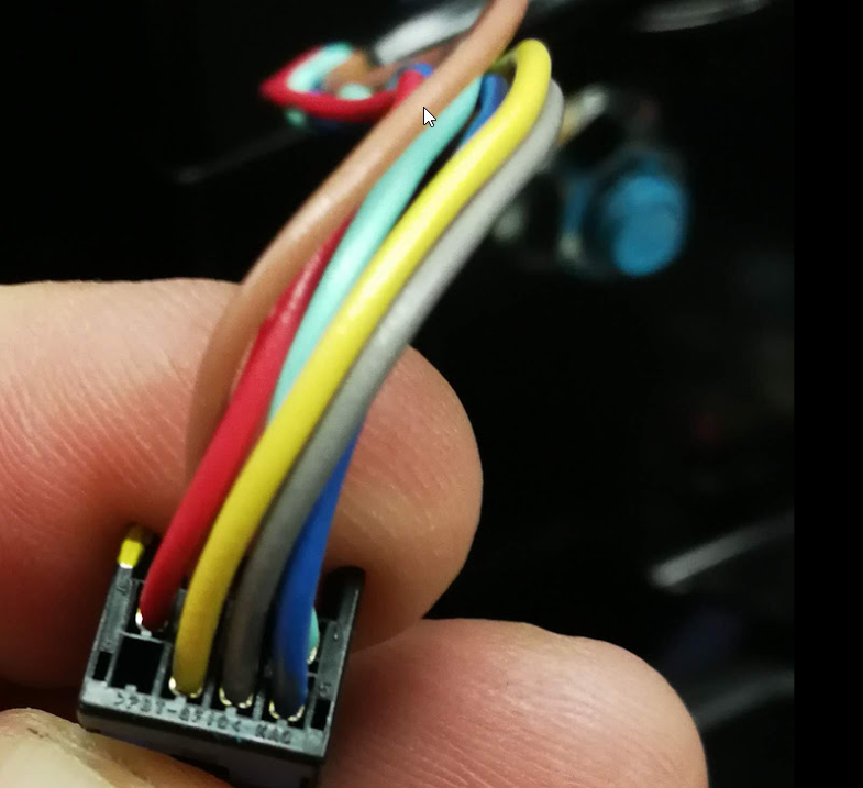
The connectors to the CMUs look like this:
This is a 8 pin connector - link and part numbers further down.
The connector has GND (pin 7), 12V (pin 1), CAN-H (pin 8), CAN-L (pin 4) wires. It has two additional wires that seem to form a some form of dead mans switch. It is a circuit that seems to go through all the CMUs and terminated at the BMU. I would imagine it is a fail safe if the CAN bus still works.
I would also imagine that if the BMU detects that the fail safe circuit is broken it will send error message on the external CAN bus.
Anyhow, it is enough to provide 12V and connect the CAN bus and the CMUs are reporting status every 40ms.

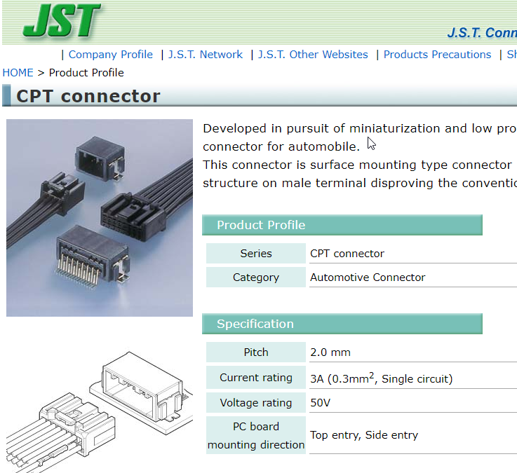
http://www.jst-mfg.com/product/detail_e.php?series=477
http://www.jst.com/home21.html
CMU - the connector is visible on the top

BMU

BMU placement

Comments (1)
Nikolay
May 22, 2020 at 12:19 AM
https://patents.google.com/patent/JP2010282816A